Structural Contraints
Nov. 28, 2020
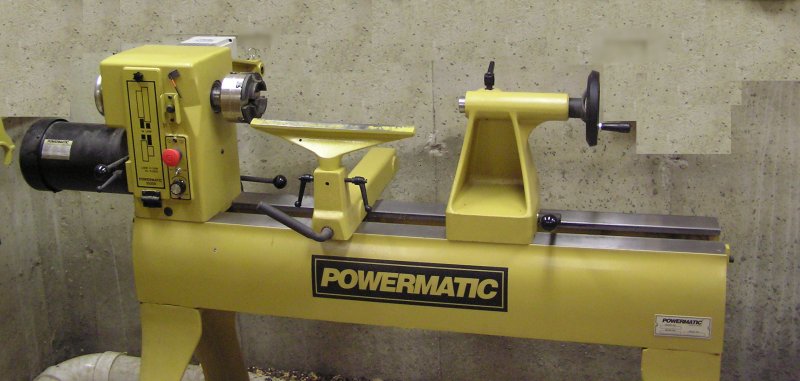
Wood-turning lathes appear in several basic designs. The most common type is for turning between centers, like this:
For face-plate turning, the tailstock isn't used, and there are two basic types of lathe. First, there's the "post style" (see Dale's Woodturnings, where he describes how this lathe was fabricated):
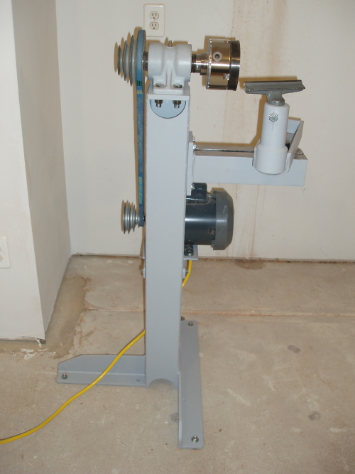
The other basic style is the "A-frame" (see Ray Makes, and his YouTube channel, where he describes this lathe). This lathe was my primary inspiration:

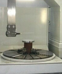
There is also the vertical style, although I have never seen one designed for wood:
The two big factors that determine whether a lathe works well are mass and rigidity. Both of these are important for any design, but some lathes rely more on one than the other. A center-turning lathe relies heavily on rigidity, and a post lathe relies almost entirely on rigidity. In contrast, an A-frame lathe relies largely on mass.
I'm interested in face-plate turning of large objects, on a sculptural scale, so the typical lathe for turning between centers isn't appropriate. The post lathe can also be ruled out since it needs to be anchored to the floor somehow, and the levering force from a weight of (potentially) hundreds of pounds is too much to resist easily. Even if the static downward-pointing force of such a weight could be resisted, the dynamic side-to-side forces would also be large. A post lathe would be very nice for turning bowls that have already been roughed out, but not for turning massive hunks that are far out of balance. A vertical lathe is an interesting possibility since the mass merely sits on a rotating table, but it raises too many difficult questions about how to arrange the cutter.
So, we're left with an A-frame lathe. One disadvantage of the A-frame design is that the wide footprint makes it awkward to access the back of the billet, particularly near the face-plate. The big advantage of this style is simplicity.
Before building the lathe, it would be good to have some numbers regarding what to expect. I'm not an engineer, and my freshman physics is rusty, but I do know how to look things up. I would be very interested to hear of any mistakes or oversights in what follows.
The most obvious question is whether the lathe will be stable. Wood is a lot less dense than steel, but it's still darn heavy. For example, a cylinder five feet across and two feet thick has a volume of \[ V = \pi\times(5/2)^2\times 2 \approx 39 {\rm\ ft}^3. \] The density of wood varies widely, depending on the species and how dry the wood is, but we're only interested in ballpark numbers, so suppose 50 lbs/ft\(^3 \); in fact, most woods are considerably lighter. A cylinder five feet in diameter and two feet thick then weighs \[ \pi\times(5/2)^2\times 2 \times 50 \approx 1960 {\rm\ lbs}, \] which is crazy. Suppose that the cylinder above has been roughed out to a bowl-like form that has walls four inches thick, with a base four inches thick. The weight of this object is obtained by subracting a cylinder that is 4 1/3 feet in diameter and 1 2/3 feet thick from above (apologies to any metric-oriented readers). The remaining volume is then \[ V = \pi\times 2.5^2\times 2 - \pi\times 2.166^2\times 1.666 \approx 15 {\rm\ ft}^3. \] At 50 lbs/ft\(^3 \), the weight would be 735 lbs. That's still a little crazy, but not entirely ludicrous. Softwoods have a density closer to 30 lbs/ft\(^3 \), for a weight of about 440 lbs. That's heavy, but conceivable.
A caveat: What follows is too optimistic (maybe "crazy" is a better word!) regarding the maximum weight that can be reasonably turned. There are two problems: building a structure that can manage a large mass, and getting that mass up to an appropriate rotational speed. Building a structure on which one could turn a 1000 lb billet is possible, but getting it up to speed is more difficult. It will become clear in the next section that no motor that I am likely to find could manage this; two or three hundred pounds is the practical limit, and even that is a stretch.
Two perspectives on the lathe are shown below. The left figure is head-on. The billet will hang from the top, exerting a downward force in the y-direction due to the static weight. There will also be a dynamic force as the billet rotates since the billet is likely to be out of balance when begining a turning, and the higher the RPM, the greater these dynamic forces will be. The right figure is from the side, showing only the downward force (y-direction). If the y-force is too great, then the lathe will fall on it's face; if the x-force is too great, then the lathe will flip over on its side. The side-view shows feet that extend out from the A-frame to prevent the lathe from tipping forward. Whether these are necessary will be considered below. A typical height for the spindle is h = 45 inches, although this could be varied slightly.
As an out-of-balance billet rotates, there will be forces in the x-direction, and these forces will tend to flip the entire lathe on its side. There are two ways to counter these forces: a wider base and a greater mass. How large could these forces be? Basic physics tells us that the centrifugal force due to a rotating body is \[ F = M\ v^2/r, \] where M is the mass of the object, v is the velocity (linear velocity, not angular velocity) and r is the radius about which the object rotates. We want to work in RPM, not feet per second, so replace v by \[ v = 2\pi r \times RPM / 60, \] and the force becomes \[ F = {4\pi^2 M\ rR^2\over 60^2}, \] where R is given in RPM.
The formula above is expressed in terms of mass, but pounds are units of weight (i.e., force) in the Imperial system. A pound is based on the downward force of an object at the Earth's surface under standard conditions. When we speak of "so many pounds," we are talking about the force exerted, not the mass exerting that force. The Imperial unit of mass is the slug, and 1 slug is the mass which is accelerated at 1 ft per second\(^2\) given a force of 1 pound. We have 1 slug = 32.174 pounds since acceleration at the surface of Earth is 32.174 ft per sec\(^2\). The upshot is that \[ F = {4\pi^2 W\ rR^2\over 32.174\times 60^2}, \] where \(W\) is the weight of the object.
Aside: in the metric system, the formula starts with kilograms, which is nice, but the resulting force is expressed in Newtons. To get back to kilograms, which are more natural for most people, you have to divide by 9.8 meters per sec\(^2\). It's a pain either way, although 9.8 is conveniently close to 10 when working in round numbers.
Suppose that you have a 50 lb weight, with center-of-mass (CM) at a radius of 3 feet, rotating at 60 RPM. This would be a dangerous thing to be anywhere near, but we need a limiting case. We then have a force of \[ F = {4\pi^2 \times 50\times 3 \times 60^2 \over 32.174\times 60^2}\approx 184{\rm\ lbs}. \] Note that this force varies with the square of the RPM so that, if the object rotates at only 20 RPM, then the force is \[ F = {4\pi^2 \times 50\times 3 \times 20^2 \over 32.174\times 60^2}\approx 20{\rm\ lbs}, \] which is almost negligible.
Most people don't have experience turning an object whose diameter is measured in feet, so, before going any further, consider what would be typical or reasonable RPMs for a given diameter. The important thing is the feet per second of material passing by the tool. When turning an object 6 inches in diameter, a reasonable RPM ranges from hundreds (for roughing-in) to maybe 2000 RPM. The corresponding linear speed is \[ S = {2\pi r R\over 60}. \] Using the example of a 6 inch diameter, with RPMs ranging from 300 to 2000 RPM, \(S\) ranges from about 8 feet per second to 52 feet per second.
Taking this range as reasonable, and using it to scale up to an object with a radius of 3 feet, we see that \[ R = {60 S\over 2\pi r} = {10 S\over\pi}, \] so that \(S\) ranging from 8 to 52 feet per second corresponds to a range for \(R\) of 25 to 165 RPM. So, in the example of above, 20 RPM for a large out-of-balance object is entirely reasonable
Before answering this question, we need another small side-trip for some physics. The force in the x-direction exerts a torque on the corner of the triangle forming the lathe's base (assuming that the lathe won't slide across the floor). Torque is given by the length of the lever-arm, times the force exerted in the direction tangent to the circle about which the torque occurs. The torque due a force in the x-direction is thus \[ \tau = F\ t\ \sin\ a = F\ h, \] where \(F\) is the force, \(t\) is the distance from the center of the shaft to the corner of the base, and \(a\) is the angle at the base.
There are two ways to counter the tendency to flip: the base can be made wider (increase \(w\)) or weight can be added to the lathe. Assuming that the weight of the lathe is centered below the spindle, this countering torque is \[ \tau = W\ w, \] where \(W\) is the weight of the lathe and \(2w\) is the width of the lathe's base. The two torques balance when \[ F\ h = W\ w. \] Using \(h = 45\) inches and a force of 184 lbs, we need \[ W\ w > 690. \] This condition is not at all difficult to meet. Getting the weight of the lathe up to 1000 pounds should be easy, and \(w\) equal to 1.5 or 2 feet seems reasonable. Moreover, a side-force of 184 lbs is an extreme case.
This question is also easiest to deal with by considering the torques involved. If the feet extending forward from the base of the lathe extend beyond the CM of the billet, then it will be impossible for the lathe to tip forward. It could bounce horribly, and walk all over the place, but it couldn't actually fall. So, modify the side-view above so that the base stops behind the CM of the billet.
There is a weight, \(W\), due to the billet, which includes both the "hanging weight," and any dynamic force due to swinging an out-of-balance billet. This weight is applied \(d\) feet in front of the base. There is a counter-weight, \(C\), the weight of the lathe, with CM at a distance \(g\) feet behind the end of the base.
The torque around the end of the feet due to the downward force, W, is \[ \tau = W\ t\ \sin\ a = W\ d, \] and this torque must be countered by \[ \tau = C\ g. \] If the lathe is not to tip, then we must have \[ C\ g > W\ d. \] Based on the calculations above, the most that \(W\) might be is roughtly 900 lbs. That is 735 lbs for a gigantic bowl-like object, plus 184 pounds due to centrifugal forces. Assuming that the lathe ends up weighing at least 1000 lbs, with \(g > d\), the lathe should remain upright. To provide a margin of error, and for safety, it may make sense to extend the base forward using some kind of feet. The downside to extending the base this way is that it may interfere with moving around the object as it is being worked on. The deeper the entire A-frame is, the shorter the feet will need to be; either option is a way to make \(g\) larger.
All the forces are transferred through the spindle, so the spindle needs to be beefy, but how beefy? The diagram below represents the spindle, with pillow-block bearings at the triangles. The spindle is drawn with a curve because it is under load, with weight, \(W\), at one of the ends. In the diagram, \(L\) is the distance between bearings, \(c\) is the distance from the bearing to the end of the spindle (the point at which the load is applied), and \(u\) is the variable distance from the bearing to the end of the spindle.
The particular curve of the spindle under load can be estimated using Machinery's Handbook. The aim is to minimize the amout of deflection, either by placement of the bearings or by choice of spindle. Many cases of beam deflection are considered in Machinery's Handbook; "Case 8," on p. 390 of the 17th edition, is closest to what we have, where it is stated that \[ y = {W u\over 6EI}(3cu -u^2 + 2cL) \] is the amount of deflection at postion, \(u\), along the end of the beam. In this formula (see p. 387), \(W\) is in pounds, \(c,u,y\) and \(L\) are in inches, \(E\) is the modulus of elasticity, and \(I\) is the moment of inertia of the beam's cross-section.
The value for \(E\) can be found on p. 425. The exact value depends on the particular alloy, but \(E=3\times 10^7\) is about right. Some steel alloys have a slightly higher value, and things like cast iron may have a much lower value, but this value for \(E\) won't be far off. The value for \(I\) depends on the cross-section of the shaft, and its diameter. It would be possible to use something like DOM tube, and that might be preferable in an industrial setting, but it's easy to get solid TGP shaft, and it is generally quite accurate. Plus, rod is heavier than tube, and any extra weight is a good thing. The value for \(I\) can be found from a table on p. 373, and the value depends non-linearly on the diameter (the fourth power of the radius). For different diameters, the value for \(I\) is
| Diameter | \(I\) |
| 1.00 | 0.0490 |
| 1.50 | 0.2485 |
| 2.00 | 0.7854 |
| 2.50 | 1.9175 |
| 3.00 | 3.9761 |
Referring to the formula for deflection, \(y\), it is clear just how much a larger diameter shaft reduces deflection. Going from a 1 inch shaft to a 2 inch shaft reduces the deflection by a factor of 16.
Let's see where we are. The deflection at the end of the beam (\(u=c\)) is \[ y_{\rm end} = {W c\over 6EI}(3c^2 -c^2 + 2cL) = {Wc^2(c+L)\over 3EI}.\] Suppose a 2 inch shaft, \(L = 16\) inches between bearings and an overhang of \(c=8\) inches. Then the deflection is \[ y_{\rm end} = {Wc^2(c+L)\over 3EI} = {W\cdot 8^2(8+16)\over 3\times3\times 10^7\times 0.7854}\approx (2.18\times10^{-5}) W.\] If \(W = 100\) lbs, then the deflection is 2.2 thousandths of an inch, which sounds pretty good. But if \(W = 1000\) lbs, then the deflection is 22 thousandths of an inch, which is not so good. It's not terrible, since turning an object weighing 1000 lbs is getting into crazy territory, but any improvement is a good thing.
Examining the formula for deflection, there are several ways to reduce the value. Using a larger shaft was already mentioned, but there's a limit to what is reasonable (and affordable). The only other variables under our control are \(c\) and \(L\). We can reduce \(c\) somewhat by putting the face-plate as near to the bearing as possible. In theory, we could make \(L\) nearly zero, but that would put too much stress on the bearings. The bearings next to the face-plate acts like a fulcrum, and if \(L\) is small, then the fulcrum magnifies the forces on the second bearing.
Use a 2.5 inch shaft (\(I = 1.9175\)), leave \(L=16\) for the time being, and reduce \(c\) to 6 inches. Then \[ y_{\rm end} = {Wc^2(c+L)\over 3EI} = {W\cdot 6^2(6+16)\over 3\times3\times 10^7\times 1.9175}\approx (4.59\times10^{-6}) W.\] That seems a lot better, but this formula isn't strictly correct, as discussed below.
There's another problem with the value determined above. The formula from Machinery's Handbook assumes that the weight, \(W\), is exerted as a point load. In fact, the object to be turned will hang off the end of the beam, from the face-plate; its effect on the beam is more like a lever than a simple point load.
One way to estimate the effect of the weight being bolted to the end of the beam is to use the equation \[ y = {W u\over 6EI}(3cu -u^2 + 2cL) \] with \(c\) equal to the distance from the bearing to the CM of the billet, and \(u\) equal to the distance from the bearing to the face-plate. This is incorrect because the billet is not part of the beam, but it shouldn't be too far off the mark. In what follows, we also use a 2.5 inch shaft (\(I = 1.9175\)), and set \(L=16\) inches. The distance from the bearing to the face-plate is taken to be 6 inches; this value is used for \(u\) in the current method of estimation. We then have \[ y_1 = {W u\over 6EI}(3cu -u^2 + 2cL) = {W 6\over 6EI}(3\cdot c\cdot 6 -6^2 + 2c\cdot 16). \] Plugging in the values for \(I\) and \(E\), this simplifies to \[ y_1 = {W \over(3\times 10^7)\cdot 1.9175}(50c -36) \approx W\times(1.738\times 10^{-8})\times (50c-36). \] If we assume that \(c=20\), so that the CG of the billet is 20 inches beyond the bearing, then \[ y_1 \approx W\times(1.738\times 10^{-8})\times 964 \approx (1.7\times 10^{-5}) W. \] This is an estimate for the deflection at the end of the beam (i.e., at the face-plate). This is greater than the earlier estimate of \((4.59\times 10^{-6})W\), because it takes into account the fact that the CM of the billet extends beyond the end of the beam.
The formula from Machinery's Handbook doesn't quite describe our situation, and one way to tweak it was just given. Here's another way. If the two ways give similar values, then we can be confident that we're on the right track.
A point load on the end of the beam has a lever-type effect on the beam. The idea of this method of estimation is to convert the weight hanging out from the end of the beam to an equivalent point load. That is, \(W_1\), as a point load, exerts a torque at the bearing of \[ \tau = W_1\times c. \] If \(W_2\) is a weight with CM at distance \(d\) from the bearing, then it exterts a torque of \[ \tau = W_2\times d. \] Equating these two torques and solving for \(W_1 = W_2(d/c)\), we can say that weight \(W_1\) at the end of the beam is equivalent to \(W_2\) hanging \(d\) inches out. Assuming that the equivalence in torque leads to equivalence of deflection, we have \[ y_2 = {W_2(d/c)c^2(c+L)\over 3EI} = {W_2dc(c+L)\over 3EI}. \] Drop the subscript on \(W_2\), and plug in the same values as before. That is, \(c = 6\), \(L=16\), and \(d=20\) for a 2.5 inch shaft. Then \[ y_2 = {W\cdot 20\cdot 6(6+16)\over 3EI} = (1.5\times 10^{-5}) W. \] This is somewhat less than the first method, but not dramatically less. To be conservative, use the first method in what follows.
It was observed above that reducing \(L\), the distance between bearings, reduces the deflection. But there is a limit to how small \(L\) may be since reducing \(L\) also increases the load on the bearings. The inboard bearing (near the face-plate) acts as a fulcrum, magnifying the force exerted on the outboard bearing. The force on the outboard bearing is \[ F_{\rm out} = {W d\over L}, \] where weight, \(W\), is exerted at distance \(d\) from the inboard bearing. As \(L\) goes to zero, this force goes to infinity. The force on the inboard bearing is then the sum \[ F_{\rm in} = W + {W d\over L}. \] The bearings within my budget seem to have static and dynamic load limits of roughly 10,000 lbs. I don't fully understand how these values are determined or their exact meaning, but suppose that we want \(F_{\rm in}\) to be less than 4,000 lbs with a maximum weight for the object (including any centrifugal forces) of 1,000 lbs. Then \[ 1 + {d\over L} < {4000\over 1000} = 4. \] This is equivalent to the requirement that \(d < 3L\) or \(L>d/3\). If \(d\) could be as large as 24 inches, then \(L\) must be greater than 8 inches. Set \(L=12\) inches for an extra margin of safety.
Going back to the calculation for the "First Method," but using \(L=12\) inches instead of 16 inches, we now have \[ y_1 = {W u\over 6EI}(3cu -u^2 + 2cL) = {W 6\over 6EI}(3\cdot c\cdot 6 -6^2 + 2c\cdot 12), \] which becomes \[ y_1 = {W \over(3\times 10^7)\cdot 1.9175}(42c -36) \approx W\times(1.738\times 10^{-8})\times (42c-36). \] If \(c=20\) inches, as before, then \[ y_1 \approx W\times(1.738\times 10^{-8})\times 804 \approx (1.4\times 10^{-5}) W. \] That's considerably less than the earlier result of \((1.7\times 10^{-5}) W\) when \(L=16\) inches.